 Loading... Please wait...
Hydrological Equipment
- Home
- Stage Measurement
- Bubbler-Type Instrumentation
- Gas Buffer Orifice
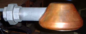
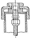
The Gas Buffer Orifice is designed to replace the USGS standard orifice fitting at the end of the orifice line on the 2” pipe that extends into the river. The Gas Buffer Orifice permits the use of extremely low bubble rates with increased accuracy and near total reduction of lag between actual level rise and orifice pressure. The chamber’s volume provides a buffer which eliminates bubbler gage lag during rapidly rising stage. Bubble rates as low as 10 bubbles per minute can be used, thereby reducing gas consumption and prolonging the life of the gas bottle or reducing the operation of the compressor.
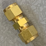
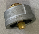
The Gas Buffer Orifice is constructed entirely of copper to deter aquatic growth and is supplied with a 2 in. union coupling that mates up with a standard 2 inch pipe. A removable screen allows for cleaning. The Gas Buffer Orifice is tapped 1/4 inch NPT to take the standard Swagelok fittings to connect to standard orifice tubing and is designed to be fitted to existing installations. The following table summarizes performance of the gas buffer orifice chamber compared with the standard orifice fitting for a water level rising at 30 ft/hr. At a 10 ft/hr. rate of rise the standard orifice still lagged significantly while the gas buffer orifice exhibited no appreciable error.
|
Float Operated Encoder (Level in Feet) |
Standard Orifice Reading | 100 Bubble/Min LAG | Gas Buffer Orifice Reading |
10 Bubbles/Min Lag |
| 0 | 0 | ** | 0 | ** |
| 2.66 | 1.9 | 0.76 | 2.66 | 0 |
| 5.57 | 3.93 | 1.64 | 5.57 | 0 |
| 7.88 | 5.05 | 2.83 | 7.87 | 0.01 |
| 11.81 | 7.53 | 4.28 | 11.78 | 0.03 |
This is a custom, special order item. Call for price and lead time.

